
Layout Introduction
LightWave’s
Layout has been designed to provide the most efficient interface possible
for your 3-D animation work. By default, there is a single large viewport,
but you can display multiple viewports if you desire. A viewport provides
you with visual feedback about the virtual world you are creating. How
well this corresponds to what the final output will look like is completely
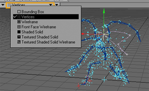
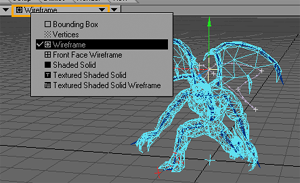
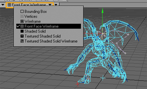
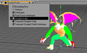
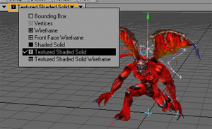
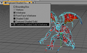
configurable by the user. This can range from bounding box stand-ins to
wireframe representations, all the way to textured and solid-shaded displays.
How you view your creations will vary depending on their complexity, your
machine’s capabilities, and other factors.
LightWave's Virtual World
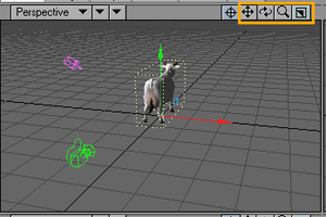
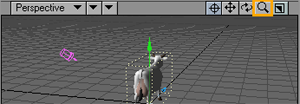
LightWave’sworld is defined using three axes: X, Y, and Z. Here we’ve loaded the COW object and haven’t rotated it. At its default position, from front to back, the cow’s body is aligned along the Z axis and is facing the the positive Z direction. The X axis runs left to right, with right as the positive side. The Y axis runs up and down, with up as the positive side.
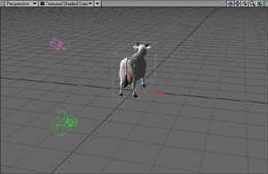
It is common to see objects that have a front and back (e.g., vehicles,
spaceships and animals) facing in the positive Z direction. As you will
understand later, this orientation works best with LightWave’s motion
features.
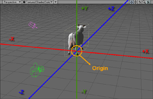
The center
of the world, called the Origin, is defined
by the XYZ coordinates 0, 0, 0 and represents the intersection of all
three axes. Any position in LightWave’s virtual world can be defined by
positive and negative XYZ values. The cow is standing right over the Origin.
(The Size
and Stretch
tools also use XYZ (scaling) values along those axes.)
World and Local Axes
Objects in a scene also have axes and, thus, an Origin, called the local Origin. When an object is first loaded, its local Origin is lined up with the world Origin. Moreover, its local axes are lined up with the world axes. However, once you move or rotate the object, this is no longer the case. LightWave provides functions that let you move and rotate items using global or local axes. Now, most of the time you’ll use World, but sometimes using local will be invaluable.
To illustrate the difference, let’s say you are standing in the middle of a one-room house facing the front door. If you held your right arm straight out, it would point to the right side of the house, and your left arm would point to the left side of the house.
Now, let’s say you turned 90 degrees clockwise. (You’d be facing the right side of the house.) If I told you to point your right arm towards the house’s right side (global axes), you’d move it straight out in front of you. However, if I told you to point your right arm to your right (local axes), you would point to the back of the house. Get it? Now sit down at your PC before someone sees you.
Your Point of View
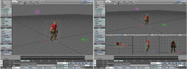
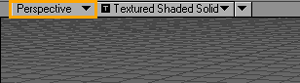
By default, Layout uses a single viewport. Later on in this chapter, you’ll learn how to use up to four simultaneous viewports! Anyway, you can choose between several different points of view (POV) for each viewport using the View Type pop-up menu at each viewport’s top-left corner. Manipulating items in virtual 3-D space on a 2-D display (i.e., your monitor) can be difficult at times, so you will switch between nearly all of these as you edit your scene.
It is sometimes easier to work in just two dimensions at a time. The options
with the axis notations (e.g., Top
(XZ))
are the “orthogonal” views, which let you move items in only two dimensions
(horizontally or vertically), along the XY, XZ, or ZY axes. The (none)setting
blanks out the viewport. Note that there are two options for each axis
set. This allows you to look in either direction along the perpendicular
axis (e.g., Top (XZ) and Bottom (XZ).
For these, Y is the perpendicular axis.)
The Perspective view is a forced-perspective view. That is, it gives you a three-dimensional look at your scene.
Note: The orthogonal and the Perspective views are dependent on each other. Changing the position of one will affect the other.
There are also pseudo-physical POVs. When setting up a light, you’ll often want to look through it to see exactly what it points at. In such a case, you’ll use the Light view to look through the current light. You’ll always want to see your scene from the Camera view at some point since that is the perspective used in your rendered images.
The Schematic View
The Schematic viewport type is a two-dimensional view showing all items in the scene as rectangles that can be selected and moved into any arrangement. You access this mode by selecting Schematic from the Viewport Options pop-up menu on a viewport’s titlebar.
Changing Your Point of View
With the View Control drag buttons located on the upper-right edge of a viewport, you can interactively alter the orthogonal and perspective POVs. The buttons obviously have no effect when you use the Light or Camera views, since those are based on their respective item’s POV in the scene itself.
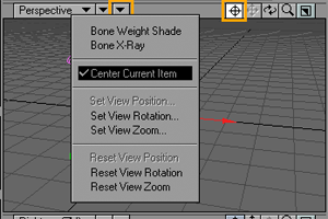
Center Continuously centers the viewport on the selected item. You may
also activate the Center Current
Item
option on the pop-up menu next to the view selector.
For an object, the centering is based on its pivot point, which is discussed later. This is not always the center of an object. If you deactivate this mode, the existing POV position will remain until changed. As such, you can use this feature to establish a starting point if the need arises.
Move Orthogonal view: Moves your POV horizontally when you drag left or right and vertically when you drag up or down.
Perspective view: Moves your POV horizontally when you drag left or right and farther/closer when you drag up or down with the LMB. Moves your POV vertically when you drag up or down with the RMB.
Keyboard shortcut: SHIFT + ALT
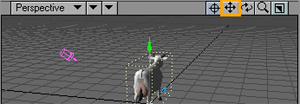
Note: Since you are changing your POV,
the scene items will appear to move in the opposite direction of your
mouse movements.
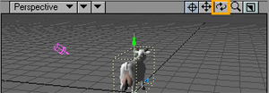
Rotate Orthogonal views: not applicable.
Perspective view: Rotates your POV’s heading when you drag left or right and its pitch when you drag up or down with the LMB. Rotates your POV’sbank when you drag left or right with the RMB.
Keyboard shortcut: ALT
Note: ALT is the same as SHIFT + ALT (i.e., Move) when used in an orthogonal
view.
Zoom All views: Zooms in and out when you drag left and right. (You can also use the < and > keys.)
Keyboard shortcut:
CTRL + ALT
Taking Aim
Both the orthogonal
and perspective views are based on a single aimpoint.
In other words, you are always looking at the same point in 3D space no
matter which of the views you use (except Light and Camera view, of course.)
It is also the center of the view rotation. That’s why, if you move around
in the Back view, it also affects the other views, like Perspective.
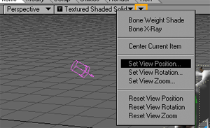
The position, rotation (affects only Perspective mode), and zoom of each
viewport can now be specified numerically using the Set View...
menu items in the viewport titlebar.
Note: If you are using multiple viewports, each has its own independent set of position, rotation, and zoom values.
Resetting Views
Also on the pop-up menu, above, are options to reset a view’s position (Move), rotation, and zoom to default values.
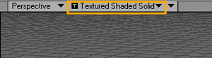
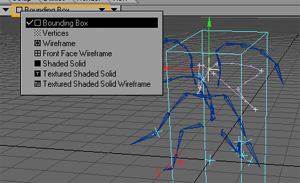
Viewport Display Mode
You can also set the display mode used by the viewport using the Viewport Options pop-up menu next to the View Type selector. This is much faster than using the Scene Editor panel.
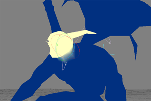
Bone Weight Shade
Activating
Bone Weight Shade in the Viewport
Options pop-up menu will show the selected bone’s influence range in any
shaded viewport. The influence coloring is based on each bone’s color,
which can be changed in the Scene Editor. A bright yellow is used for
the currently selected bone. Note that the bone must be active to see
this effect. This mode will override the normal texture display.
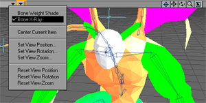
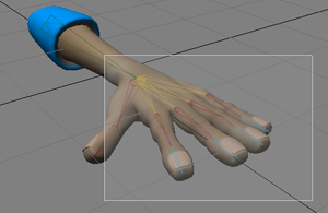
Bone X-Ray
There is an option to make bones visible inside opaque objects. To use, activate the Bone X-Ray option on the titlebar. Note that bones may still be invisible if the object surface is similarly colored/shaded. Change the bone colors using the Scene Editor, if this becomes a problem.
Recipe for a Scene
LightWave animations (or still images) always start as a Scene —basically, a collection of objects, lights, cameras, and images, which can move and change over some specified length of time. Creating a basic LightWave scene involves the following steps:
• Adding items
(e.g., objects and lights) to a scene
• Setting the starting position for all items in the scene
• Setting the length of the scene
• Placing items in key positions at certain points in time
• Previewing the motions of the items
• Setting and testing render settings
• Rendering the final animation
Selecting an Item in Layout
Usually, you work on one item at a time, the current item, and you need to tell LightWave which item it is. But before you learn how to do that, you need to know that Layout items are grouped into four different types: objects, bones, lights, and cameras. When you work on any item, the edit mode buttons along the bottom (i.e., Objects, Bones, Lights or Cameras) are set to the current item’s type.
To select an item:
There are several ways to select an item in Layout:
• Click on
the item in a viewport;
• Click on the item’s name in the Scene Editor panel (Scene
Editor); or
• Manually select the edit mode and then select the item from the Current Item pop-up menu. Note that
you cannot select a locked item (a little lock icon appears next to name).
• Use the Item Picker master plug-in
• You can select items in a viewport by clicking on any polygon edge rather
than just on a pivot point.
Note: You can use your UP and DOWN ARROWKEYS to cycle through the Current Item list.
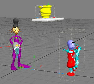
All items, except objects, are highlighted in yellow when selected. When an object is selected, a dotted-yellow bounding box will appear around it.
Note: You can select a bone by clicking near its midpoint, rather than its pivot point, making it possible to pick different bones that branch from the same point in a hierarchy.
Selecting Multiple Items
You can select multiple items of the same type, like all objects or all lights, and perform edits on them simultaneously.
To select multiple items:
Holding the SHIFT (or CTRL) key will allow you to select multiple items of the same type.
If you select multiple items, many operations will be applied to all of them. This can save a lot of time under the right circumstances. Such operations include Move, Rotate, and Size, as well as certain item properties, like Unseen by Rays, Unseen by Camera, Self Shadow, Cast Shadow, Receive Shadow, Bone Active, Affect Diffuse, Affect Specular, Affect Caustics, Affect OpenGL, and so on.
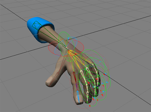
Multiple
Bones in the Hand Object Selected and Rotated
If the toolbar command is a state-type command and the selected items have mixed settings, the button will be shaded diagonally. Clicking the button will toggle the state of the current item and make all other selected items the same. Clicking again will toggle the state of all items.
Selecting by Name
Pressing the apostrophe (‘) key launches a special selector dialog. Simply type-in a few characters that uniquely identify the desired item and click OK. You can select any type of item.
Unselecting Items
In Layout, one item is always selected. It becomes unselected when you select a different object.
Item Selection: Bounding Box
A selection bounding box--like in the Graph Editor--can be created by dragging your middle mouse button in any viewport. Items whose points appear within the box will be selected, and if the Shift key is held down, the items will be added to the existing selected items, if they are the same type. If items of more than one type are within the box, preference is given to those items matching the current edit mode.
HINT: If you have a scroll wheel, it may also function as a middle mouse
button if you press down on it. This obviously depends on the make and
model of your mouse.
