Layout's Window Drop Down Menu
Motion Mixer
Motion Mixer (Window> Motion Mixer) was designed to bring the same concepts found in non-linear video editing to computer animation. You can store, re-use, and adjust motions for entire hierarchies. You can even mix motions together.
Note: For more information about Motion Mixer see the Motion Mixer section.
Presets
The Preset Shelf is a sizable floating window that holds a list of previews along with all of the associated settings in Layout. It can be used for settings with surfaces, volumetric lights, hypervoxels, etc. It is accessed using the Presets button (Windows> Presets) or from some plug-in panels.
Note: For more information about Presets see the Preset Shelf Section.
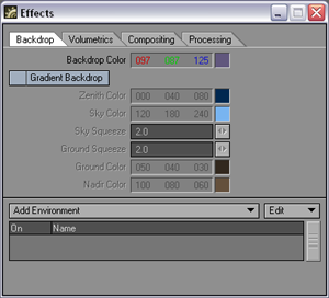
Backdrop Options
LightWave lets
you change the colors of the backdrop behind all of the objects in a scene.
The settings are on the Backdrop tab of the Effects panel (Window
> Backdrop Options). You can elect to have a solid color using
the Backdrop Color setting or a gradient color backdrop. By default, the
backdrop is solid black.
Note: If you have any reflective surfaces
and you want the backdrop included in the reflection, set the Reflection
Options on the Surface Editor’s Environment tab to one of the backdrop
options.
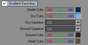
Gradient Backdrops
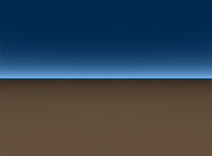
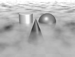
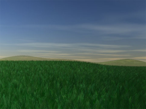
LightWave’s Gradient Backdrop settings essentially provide a quick earth-like environment background. Note that no shadows can be cast on the backdrop since it really isn’t there. Although you’ll likely not use it much for real-life imagery, it is great for faking a sky behind mountain objects, instructional animations, and logo animations. Use it when you need something to stick in the background.
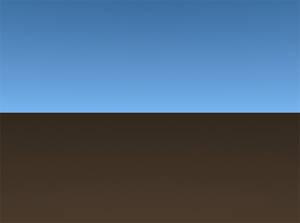
There are
actually two gradient areas. Think of it as a huge sphere cut into two
halves. One half rests on top of the Y axis plane, and the other half
sits directly beneath it.
The Sky Color
begins all around the edge of the top half of the sphere and gradually
turns into the Zenith Color moving towards the top. The Ground Color
begins all around the edge of the bottom half of the sphere and gradually
turns into the Nadir Color moving towards
the bottom. Note that there is no gradual change of color between the
Sky Color
and Ground Color.
HINT: If you want the Gradient Backdrop to blend everywhere with no sharp color change, make the Sky Color and Ground Color the same.
The camera is always positioned right in the center of the sphere. Thus, if you move the camera, the Gradient Backdrop will always look the same. However, if you rotate the camera, you will see the various colors.
The Sky Squeeze value determines how the Zenith and Sky colors are blended. The Ground Squeeze value determines how the Ground and Nadir colors are blended. The default value of 2.0 yields a nice spread between the various colors. A lower value will spread the change in colors over a greater area and a higher value will compress the change.
Sky
and Ground Squeeze both at 20.0

HINT: The default gradient colors are
useful when simulating a reflective chrome surface.
Environments
Several plug-ins
may be used to create exciting backgrounds for your animations. You access
these plug-ins by adding them on the Add
Environment pop-up menu on the Backdrop tab of the Effects panel.
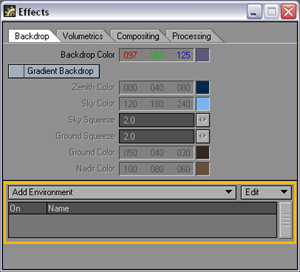
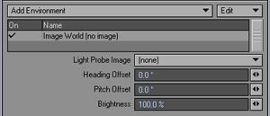
Image World
The Image World Environment lets you apply an image as a spherical environment wrap; this approach is perfect for high dynamic range images. You can offset the heading and pitch of the image, as well as adjust its brightness.
Textured Environment
The Textured Environment lets you apply a texture as a spherical environment wrap; this approach is perfect for high dynamic range images. Clicking the Texture button launches the standard Texture Editor giving you access to gradients, procedurals, and the use of images to create an endless variety of textures.
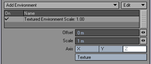
The texture
is not stuck
to the camera background, like a normal background image, so as you move
the camera, you will pan over the environment.
An interesting application would be to use a gradient and select the (camera) Heading or Pitch as the Input Parameter. This lets you vary a glorious sunset sky based on the rotation of the camera. You might also use this to add a cool nebula behind your starfield using a simple Turbulence or Fractal Noise procedural texture.
Note: For more information on the Texture Editor see the Texture Editor section.
SkyTracer
The SkyTracer Environment was designed to create sophisticated atmospheric effects using real-world parameters.
Note: This is a legacy tool replaced by
SkyTracer2 and NewTek recommends that you only use this to read loder
LightWave scene files. SkyTracer2 offers all these features and is far
more robust.
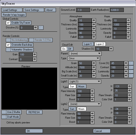
SkyTracer2
The SkyTracer2 Environment was designed to create sophisticated atmospheric effects using real-world parameters. You can adjust the atmospheric, cloud, and sun settings within the interface to create a variety of beautifully rendered sky images. These skies can be rendered (volumetrically or as a 2-D effect) within an existing scene, or saved as image files to be composited or used as texture maps.
Note: For more Information about SkyTracer2 see the SkyTracer2 section.
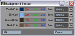
Background Booster
The Background Booster tool (Window>Background Booster) gives you the ability to easily edit the background gradient settings. Use the Boost function to multiply each of the RGB values by the boost percentage.
Volumetrics and Fog Options
LightWave
features volumetric effects—essentially lighting and particle effects
with physical volume. These effects are common in everyday life and can
play a key role in creating dramatic realistic environments. However,
they are difficult to reproduce using standard polygonal models.
Copyright
Pixel Magic
Background
A very common example of volumetric lighting is the atmosphere: the color of the sky comes from the scattering and absorption of light in the different layers of the atmosphere.
The combination of light scattering and absorption is the very core of volumetric lighting effects. Additionally, other parameters must also be taken into account, like volume size and shape, density distribution inside the volume, lighting conditions, and behavior of light inside the medium. Adjusting these parameters lets you create a wide range of natural effects.
The sky, for example, is usually blue because light attenuation depends on wavelength and distance. When the sun is at the zenith, its light crosses fewer layers of atmosphere than when the sun is on the horizon. Blue light is stronger at the zenith than at sunset because the thinner atmosphere does not interfere with its shorter wavelength. In Red sunsets, the thicker layers of atmosphere attenuate blue light, but the longer wavelength of red light passes through the atmospheric layers.
Fog is another good example. It is a medium composed of vaporized water where density is distributed in a non-homogeneous manner. The water particles in the fog cause a dispersion/absorption phenomenon that causes the lighting effect, while the density distribution gives the global appearance of the fog. If you want a thick fog lying on the ground and fading with altitude, you will have to use a density distribution that makes the density high at lower altitudes and low at higher altitudes. If you want to add turbulence in the fog (to have a more cloudy appearance), you can add fractal noise, which creates a 3D density field.
Computational Issues
Volumetrics are calculated by integrating all the scattering/absorption contributions along a ray (which comes from the camera). When you use a 3D fractal density field, the integration must be made numerically with a limited number of sampling points. In this case, the values will be calculated at each sampling point, which means that for 50 sampling points, the algorithm calculates 50 density field values, 50 lighting values, and 50 scattering/absorption values. All those values can take a lot of time to compute. Using fewer sampling points will result in a faster rendering but will introduce numerical errors: this is volumetric aliasing. Volumetric shadows can be obtained this way by measuring the lighting conditions at each sampling point along the ray.
When you work with a normal density distribution, you can make the integration literally, which gives a much faster rendering. But in this model (which we call fast model), it is not possible to measure lighting conditions along the ray, and as a consequence it is not possible to get volumetric shadows.
Another important note about numerical issues is how to adjust values to get the desired effect. The intensity of the effect is always related to the length of the medium crossed by the ray. This is obvious if you compare cigarette smoke to smoke from a large fire—the size of the volume has a big influence on the result. The behavior of light may also change completely when the volume size changes, because absorption may overpower scattering, and vice versa. A good example of this is clouds.
When you look at clouds, you see that small thin clouds are bright and totally white, while big clouds have dark gray areas and a thin white border. The dark gray color comes from the absorption of light inside the cloud. Even the scattering of light emitted inside the cloud is absorbed from the point of scattering to the boundaries of the cloud. In this example, absorption takes precedence over scattering when thickness gets bigger. However, under other circumstances, the opposite could occur. When you use high absorption and scattering values, you can create explosion-like effects, where there is very high contrast between bright and dark areas. In conclusion, when adjusting parameters, you must be aware of the scale of the object you are working on.
About Particles
When you work with particles, a sphere of gas is associated with each particle. As a result, a particle cloud is really just a union of spheres. Computing the effect for every particle can be computationally intensive, particularly when their spheres overlap one another. The solution is the automatic particle sizing option, which evaluates a particle size so that each particle is close to another. The result is a dense cloud optimized for numerical integration and lower rendering times.
Normal Fog
LightWave can generate a quick fog effect that is useful for many special effects. Just as objects seem to blend into real fog with distance, the effect fades the objects away into the fog color you set. Fog surrounds the camera in all directions, as though the camera were in the middle of a huge spherical fog bank extending in all directions.
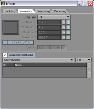
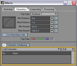
The fog settings are on the Volumetric tab of the Effects panel (Window> Volumetrics and Fog Options). In setting up fog, you will set a minimum and maximum distance from the camera. Within and beyond this range, objects will take on some amount of the Fog Color. You can also specify the percent of fog color that objects take on at the minimum and maximum distances.
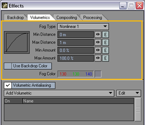
The Fog Type
pop-up menu sets the characteristics of your fog. Off,
obviously, turns off the fog effect. The other fog types differ in how
the effect falls off toward the camera. Linear
falls off in a linear manner. Nonlinear
1
is somewhat more realistic in appearance, since the fog will appear to
grow thicker with distance. Nonlinear
2
has a steeper falloff curve.
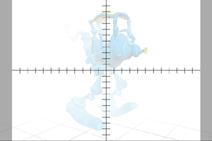
It’s important
to realize that the Fog feature doesn’t actually calculate a wispy volumetric
fog around objects, but rather changes the color of the objects to that
color chosen as the Fog Color. As such, the
backdrop will receive no amount of fog. For volumetric 3D fog, use the
GroundFogvolumetric, discussed later.
A negative Minimum Distance will start the fog behind the camera. You can even enter a larger minimum amount than the Maximum Distance amount, which results in an effect whereby objects will render in more of the fog when closer to the camera.
By default, fog is applied linearly between the Minimum Distance and Maximum Distance. Non-linear options are also available, which apply the fog amount more rapidly as they are moved away from the camera, then less so as they approach the maximum distance. The small graph to the left of the setting gives you an indication of the fog application over distance.
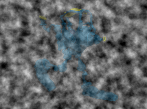
The Use Backdrop Color option causes an object to blend in with whatever backdrop you have set, including a background image. This can have the effect of making objects appear slightly transparent. Use this option to simulate the effects of an underwater environment or a hazy, foggy day with an appropriate Backdrop Color like bluish green for underwater and grayish white for a foggy day.
If you add the Texture Environment environment (Window > Backdrop Options) and also activate Use Backdrop Color, your fog (and backdrop) can use a texture.
Note: The rendering speed of the Fast
Fog Render Type for the Ground Fog volumetric comes at a price. Because
it is not a full volumetric effect, it will not always blend accurately
with other volumetric effects, like volumetric lights. This may result
in visible artifacts in your rendered images.
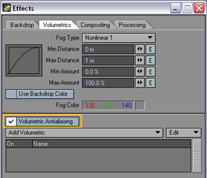
Volumetric Anti-Aliasing
The Volumetric Anti-aliasing option activates or deactivates the anti-aliasing of volumetric plug-ins and volumetric lights. If this option is off, the volumetric effects from the first rendering pass are stored and reused in later passes, instead of being re-rendered in each pass. Obviously, this can save rendering time, but will require more memory and may cause problems when used in conjunction with motion blur or depth of field.
Volumetric Plug-ins
Volumetric Plug-ins are added on the Volumetrics tab of the Effects panel.
Ground Fog
Use the Ground Fog volumetric plug-in to add three-dimensional fog to your scene. The fog has actual physical size so, for example, the camera can move in and out of the fog. This differs fundamentally from normal fog, discussed previously, where the camera is always within the fog.
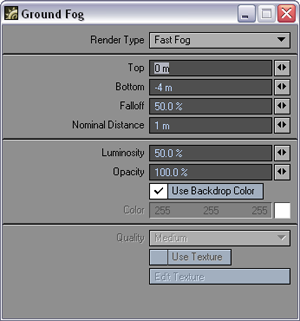
With the
Render Type
pop-up menu, you can choose between two different types of Ground Fog.
Fast Fog
is a quick-rendering fog with a uniform thickness. It is basically the
three-dimensional version of normal fog. Ray Marcher
adds an uneven fog, particularly when you use a texture. Since this fog
varies by precise physical position, like real fog, it is computationally
intensive, but generally yields a more accurate and realistic result.
When using Ray Marcher, you can throttle the amount of computations using the Quality pop-up menu at the bottom of the panel. Add a texture by activating the Use Texture option. Clicking the Edit Texture button will bring up the standard Texture Editor. A fog texture will make your fog more interesting and less flat.
The Top and Bottom settings control the altitude of the fog, that is, where your fog starts and stops vertically. Falloff determines how the fog decreases to zero, from the Bottom to the Top. The higher the value, the more the fog will decrease its density. Note that the Ray Marcher mode tends to fall off quickly at the fog’s edges, while Fast Fog has a uniform linear fall off.
Note: Make sure you know where your camera is when using GroundFog. The effect is really best seen from outside of the fog. If your camera is inside the fog, changing settings may appear to have little effect. In fact, if your camera is always within the fog, you may want to just use the (faster) normal fog.
The Luminosity and Opacity values are the values where the fog is at its thickest.
Nominal Distance is the distance at which the fog has a medium effect—it is not like standard Fog’s Minimum Distance. You will want to use small values for small-scale scenes. Large-scale scenes may require higher values to keep close objects from getting too affected by the fog.
You can set the color of the fog with the Color setting or you can just use the backdrop color.
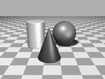
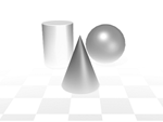
Left,No Fog-Middle,
FastFog-Right, Ray Marcher Fog using a Texture
HyperVoxels
With ordinary polygonal objects, realistic effects like liquids, smoke, clouds, and fire are difficult, if not impossible, to achieve without HyperVoxels. It simplifies the creation of volumetric rendering effects such as photo-realistic clouds, flames, explosions, dust, nebulas, contrails, fluids, smoke, ash, pyroclastics, gelatin, electro-microscopic images, rusted materials, detailed solid and rocky surfaces, and much, much more.
Note: For More Information about Hypervoxels see the Hypervoxels section.
Compositing Options
Background Image
The Background Image is similar to the gradient backdrop; however, it is always registered to the camera. That is, it will always appear in exactly the same position/location no matter which way you tilt or move the camera. You set this option on the Compositing tab of the Effects panel. Background images are considered infinitely distant from the camera. You can never have an object behind a background image, nor can you light a background image or cast shadows upon it.
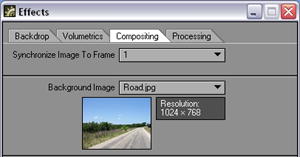
Background
images stretch to fit the Camera resolution and frame aspect that you
are using. Make sure to use similar-sized background images if you wish
them to match.
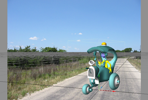
You often use background images to merge live action and 3D elements, like creating the illusion that a UFO crashed into the Empire State building. An image of the New York skyline would be the background image and the UFO would be a LightWave object.
Note: Background images are visible only through the Camera View.
HINT: If you actually need your background image to interact with objects, use the image as a Surface Color Texture mapped on a flat plane object and place the plane at the back of your scene.
If you set Camera View Background on the Display Options tab of the Preferences panel (Display > Display Options) to Background Image, you will see the set Background Image in Layout’s Camera View. Of course, actually seeing the background in the Layout window is optional. The background image will always appear in the rendered frame.
Note: Displaying background in the Layout
window, particularly a color one, is processor intensive, so use this
feature sparingly.
The whole idea behind traditional image compositing is quite simple: take two or more images, and merge them into a new composite image. LightWave lets you do this, but also takes it one step further by letting you throw objects into the mix.
The images can also be a sequence of pictures, so you may use captured video footage as a background for your objects. A simple example would be a modeled UFO moving against a real sky and trees. Images can appear behind all objects, in front of all objects, or a combination of the two with objects showing in between.
Compositing can be a render time-saver. If you set up a scene with many objects, but only a few are moving, you could render one frame with only the inanimate objects, and then remove all of those objects and render the animated objects against the single frame saved earlier. This is especially useful when the still objects are complicated or involve ray-traced shadows, refraction, and/or reflection.
Foreground Images
Placing an image in front of everything may seem like a silly thing to do. However, some options let you cut parts of the image away so you can see through it. You can also make the image partially dissolved or even envelope the dissolve. Dissolving in a black image in the foreground will produce the common fade-to-black effect, or reverse the dissolve to fade in from black.
You can make holes in the foreground image based on a defined color range in the image. However, the biggest drawback to simply clipping out portions of the foreground image is that you will have hard edges. A color is either clipped or it isn’t, so you see either the foreground image or the background image.
Use the Foreground Image pop-up to set the foreground image.
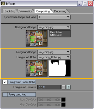
Alpha Images
You may also use a special alpha image to merge the background and foreground images. This type of alpha image is very different from the type you use to set up a transparency surface texture. LightWave composites the foreground image over any objects or background by adding their colors to the foreground image. How much background is added is determined by the alpha image. The darker the area of an alpha image, the more the background is added to the foreground. The pseudo mathematical equation might look like:
Foreground + (1 - Alpha) * Background
If you used the same exact image for both the background and foreground images, plus a solid black image as the alpha image, you will receive a final rendered image where every pixel is twice the color value it was. This results from the background image being completely added to the foreground image.
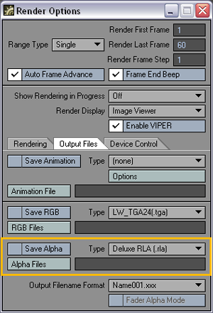
Creating Alpha Images
Generally, alpha images will be generated when you render a scene to create the foreground images. When you select Save Alpha on the Render Options panel’s Output Files tab (Render > Render Options), LightWave will generate and save an alpha image in addition to the normal RGB output. The alpha image will be composed of grayscale values representing the opacity of any objects that were rendered in the scene.
An object
that contains no transparent surfaces will be rendered as solid white.
Transparent surfaces will render in some shade of gray depending on how
transparent they are. One hundred percent transparent surfaces render
as black. A 50-percent transparent surface will render as 50-percent gray.
Using object dissolve, anti-aliasing, motion blur, and so on. will also
give you values other than white in an alpha image. Any background (image
or colors) will be black in the alpha image, as will any additive effects
such as glow or lens flare.
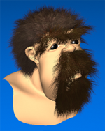
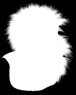
Image and
Alpha
Since glows and lens flares are additive effects and are assigned a value of black in an alpha image, glows and lens flares in the actual foreground image will simply have the background values added, so they will appear brighter where the background is a value other than black.
HINT: Generally, due to LightWave’s additive compositing method, foreground images are created using a solid black backdrop. This allows the composited background to show through unaltered when it is mixed 100 percent with the foreground.
Foreground Fader Alpha
What happens if you want to composite a foreground element on top of objects or a background, but the foreground image was not rendered over black? In this case, LightWave provides a Foreground Fader Alpha button that can be selected. In this mode, LightWave will ignore any areas of the foreground image corresponding to black areas in the alpha Image. These areas of the foreground image will be faded away to nothing so you see 100 percent of the background instead.
When using Foreground Fader Alpha, glows and lens flares will not be added to the final rendered image (their corresponding alpha is black) unless you are using a different alpha image containing non-black areas in those locations. Additionally, antialiased object edges most likely will stand out because they contain bits of color from the original non-black background.
Foreground Key
Activate Foreground Key when you want to key out (i.e., not render or see) a color (or range of colors) from the foreground image. Use the same color value for both Low Clip Color and High Clip Color if you wish to key out one color only. Use different values to key out the Low Clip Color and High Clip Color values, and all those in between.
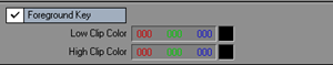
The Low Clip Color
is the color value for the darkest color value that will be keyed
out. High Clip Color is the brightest
color value that will be keyed out.
HINT: If you want to create a giant space battle and lack the RAM to hold all of the objects and image files, you could composite layers of ships and achieve the same results. This is, in fact, how some broadcast TV shots were done using machines with only 32MB of RAM in the early days of LightWave.
Image Processing Options
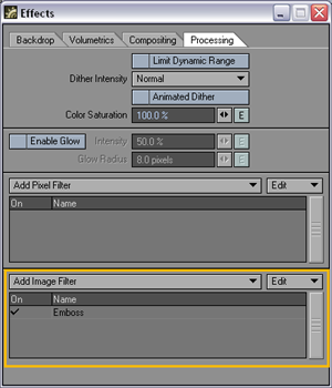
The Processing tab on the Effects panel contains functions that apply effects to the rendered image. Choose Window>Image Processing Options to directly bring up the Processing tab of the Effects panel.
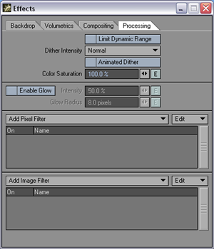
Limit Dynamic Range
Limit Dynamic Range clips the pixel color components of each rendering pass at 1.0, improving the antialiasing of extremely bright areas. This option should not be used with filters or image savers that expect high dynamic range data.
Dither Intensity
Dithering blends two colors to simulate a third color between them, forming a more realistic blend. Dither Intensity lets you set the amount of color blending used by LightWave when rendering an image. Even with 24-bits of color data, it is possible to perceive color banding where distinct changes in color or brightness occur within otherwise smoothly ramped colors. Off removes all dithering, and you will probably experience some color banding. Normal, the default setting, reduces banding to the point where it nearly disappears. 2x Normal increases the dithering even further, which may be useful for high-end systems that still retain some appearance of banding in the final image. 4x Normal boosts dithering so that the resulting image looks more grainy, like film, which may be a desirable effect (especially when used with Animated Dither, below).
Animated Dither
Select Animated Dither to change the dithering pattern used from one frame to the next. This ensures that dithering is randomly placed, so there is no apparent pattern to the dither blend. With a 2x Normal or 4x Normal Dither Intensity, this can be used to approximate the randomness of film grain moving through an image.
Color Saturation
Color Saturation lets you control the amount of color in a scene (or in an animation, if using an envelope). Saturation at 100% is a normal, full-color setting, while saturation at 0% is a black and white setting.
Glow Settings
When Enable Glow is turned active, LightWave can add a glow around surfaces with a (surface) Glow Intensity above 0%. Use the controls below to set up the amount of glow you wish to add to all such surfaces.
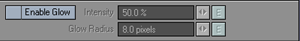
Glow Intensity
sets the brightness of the glow, starting from the edge of the surface
itself and fading away from there. Glow
Radius
sets the distance (in pixels) that the glow extends from the edge of a
glowing surface. Note that different resolution settings will cause dramatically
different results.
Image Processing: Pixel Filters
Pixel filters let external applications affect LightWave’s rendering engine. Filters in this class can be affected by motion blur and other sub-frame operations during the render rather than as a post process, as image filters are.
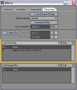
Halftone
In print, halftone screens are made up of dots that control how much ink is deposited at a specific location. Varying the resulting dots’ size and proximities creates the illusion of variations of grey or continuous color.
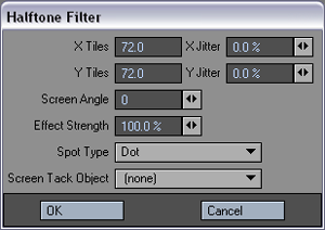
The X Tiles
and Y Tiles
values determine the number of possible horizontal and vertical dots.
If you would like to randomize either of these settings (throughout your
animation), use the corresponding Jitter fields.
In the photography world, this type of effect is achieved with a (physical) screen that breaks up the image into dots. Think of the Screen Angle setting as the rotation of that screen. It controls the angle of the dots.
You can control the overall amount of effect by adjusting the Effect Strength setting. Settings below and above the default of 100% are allowed.
You can change the pattern by changing the Spot Type. Specify and animate a Screen Tack Object to animate the pattern position. The OK button stands for Ocular Kinesthetics. It lets the filter change pixels that will then be perceived by the ocular nerves.
![]()
![]()
Left:
Without Halftone, Right: With Halftone
LW_Hypervoxels and LW_Hypervoxels_Doubler
These two image pixel filters are Legacy tools for rendering older LightWave Scene files that use older versions of Hypervoxels.
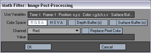
Math
Filter
This pixel Filter allows you to use a mathematical formula to adjust the
color in your render.
SasLite
Sasquatch Lite allows you to quickly and easily create a variety of effects such as grass, fur, and hair on your objects. Sasquatch Lite uses its own rendering engine to render the hairs quickly and combine the results seamlessly with your LightWave objects. Sasquatch Lite is a very simplified version of the commercial plugin Sasquatch from Worley Laboratories.
Note: See the discussion on the “Sasquatch
Lite” displacement plug-in located in the Sasquatch Section
for more information.
Skytracer
The SkyTracer Environment was designed to create sophisticated atmospheric effects using real-world parameters.
Note: For more information see the section on SkyTracer 2
Steamer and Steamer_Doubler
These two image pixel filters are Legacy tools for rendering older LightWave Scene files that use Steamer.
Image Processing: Image Filters
Image filter, unlike Pixel filters in the previous section, act on an image as a whole. They can be used for a variety of things, from saving out a layered Photoshop file to achieving a light bloom effect on your render, or making it into a sepia or monochrome image. Some of the filters can be applied directly to images you use within LightWave - for instance, full precision blur can be used to soften black and white images intended for a bump map.
Image filters are a post-process effect. This means that they get applied only once all rendering has been performed. Some of them, such as Digital Confusion, by their very nature need your picture to be rendered as one segment otherwise nasty banding effects can occur.
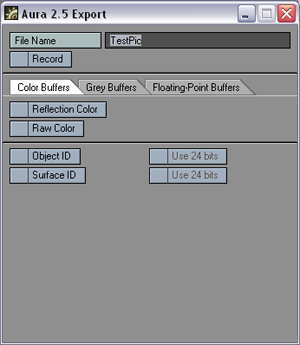
Aura 2.5 Export
The Aura 2.5 Export image filter has access to all the different internal render buffers and can export them to Aura. Aura 2.5 can then take this information and manipulate it with it's many features and options.
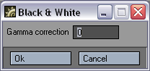
Black & White
Creates a Black and White veriosn of your render. Double clicking on the item in the list will bring up the Back and White panel where you can alter the gamma correction for the contrast levels.
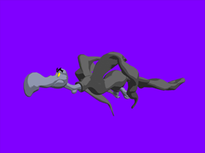
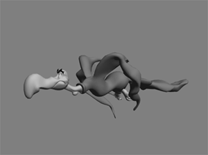
Left:
Normal Render, Right: Black and White Image Filter Applied
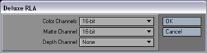
Deluxe RLA
This image filter allows you to set the format for the color, matte and depth channels for the RLA format.
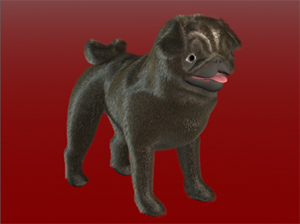
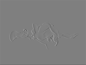
Emboss
Emboss makes a render appear raised or stamped by converting its color to gray and tracing the edges with the original fill color. The embossed edges are the colours the objects originally had.
Left:
No Filter, Right: Emboss Filter
Emboss Black and White
Emboss BW makes a render appear raised or stamped by converting its color to gray and tracing the edges with the original fill color.
Flare2Alpha
This image filter will add lens flares to the alpha of your rendered image
as opaque objects so that they get composited in. Normally lens flares
are a post processing addition to the render and so don't get figured
into the alpha channel.
Gamma
This is a Legacy filter. Gamma adds a gamma of 2.2 to your image brightening
it a little. This plug-in is pretty much devalued since LightWave has
had the ability to render full precision images and shouldn't be used.
Instead use Full Precision Gamma.
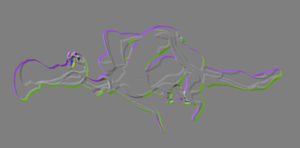
Anaglyph
Stereo: Compose
This filter allows you to recreate the kinds of stereo images used with
glasses with red and blue lens. By choosing this image filter and also
setting up stereoscopic rendering in the Camera Properties panel in the
Stereo and DOF tab at the bottom of the window, your render will have
the two channels, one for each eye, combined into a single red/blue image.
Using the Quicktime Stereo animation type in Render Options will allow you to save a stereoscopic animation. You need to render at least two images to see the stereoscopic ones.
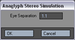
Anaglyph
Stereo: Simulate
For cases where you want the look of the stereoscopic effect, but don't
want to render two images, or you just want to see what effect the stereoscopic
camera in LightWave is capable of, there's the Simulate filter.
Bloom
This filter imitates the way that sometimes too much light is reflected
back into the camera from a brightly lit scene. The effect is often seen
when photographing or filming shiny metal surfaces or water.
Sometimes light reflections in the real world are so bright that too much light will enter a camera lens, over-saturate areas, and create a glare or a glowing halo. Shiny metallic objects like cars and water often exhibit this phenomenon. Bloom will mimic this effect.
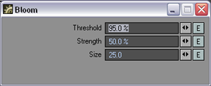
The setting
for this filter allow you to set a Threshold for the effect
– how bright a pixel has to be before it blooms. Strength
is how bright the bloom effect is compared to the pixel it is overwriting
and Size
is the size of the bloom brush that is used to replace a pixel rendered
at a 640 x 480 resolution. If you use a size that looks correct on your
320 x 240 test render, it will still look the right size on your 2000
x 1200 final print resolution render.
Note: Use the Bloom filter for a simple over-exposure effect. Use Corona if you need more control over your bloom.
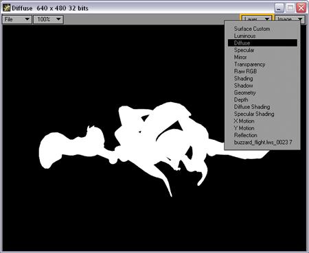
Render
Buffer View (Post-processing only)
This filter makes the selected internal buffers visible as separate images
when you use the Image Viewer.
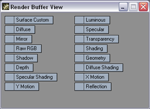
Use the
Layer Drop Down list on the
Image Viewer
to choose the internal buffer you would like to view.
Chroma Depth
The Chroma Depth filter makes a stereo image for use with Chroma Depth
glasses (see www.chromatek.com). Basically, color determines the apparent
depth in the image.
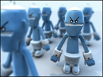
Render with Chroma Depth Applied
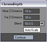
This filter
recolors the scene based on the Z-depth; it spreads the spectrum of colors
from the Near Z Distance to the Far Z Distance. Blend dissolves the Chroma
Depth image in with the regular colors to make the depth effect subtler.
Auto-Scale finds the actual near and far for you when it renders - you can render once with this option on and the calculated values will appear in the fields.
Corona
This is a more fully featured version of Bloom. With it you have a lot
more control over what causes blooming. In essence, control is broken
down into which input channels cause blooming, how the bloom takes place
and some additional abilities not found Bloom.
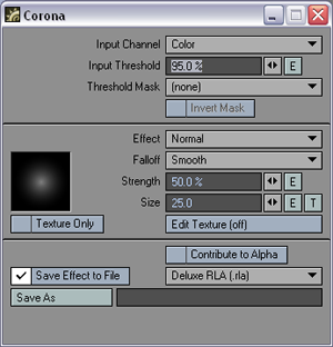
Input Settings
Input Basis lets you choose which internal buffer to read for the bloom effect, so you can bloom on specularity, bloom on diffuse, and so on. The Input Basis acts like a trigger: when its value exceeds the Input Threshold, the effect is applied to that pixel.
Color uses raw pixel values—essentially any pixel on screen that is bright enough gets bloomed. Alpha uses alpha’s pixel values—0 to 100% for the image. Specular Shading uses 0 to 100% of surface specularity as shaded during the rendering. This varies over a given surface and is different from the Specular surface channel, which is uniform over a surface. Diffuse Shading is similar, but uses the diffuse surface property.
Geometry uses the normal of object surfaces, where 100% indicates that the normal points at the camera. Inverse Geometry is similar, but 100% indicates that the normal points perpendicular to the camera. These are easily demonstrated using a sphere. For Geometry, the center of the ball would trigger Corona, while Inverse Geometry would result in the effect along the edges.
Special uses the surface Special Buffer feature on the Surface Editor. The value of the Special Buffer is compared against the threshold and when it exceeds that value, the Corona filter is applied.
The input can also be masked to skip areas of the input altogether. Threshold Mask is basically an alpha channel. Brighter areas will be susceptible to the mask, while darker areas will not.
Effect Settings
The Effect pop-up menu selects your blending mode. Additive yields very hot (white) results where triggering pixels are closely grouped. This is useful for, say, obtaining the look of metal being heated. The center of a block of metal will become super hot while the edges do not. Normal is similar to Additive, except in the case of heated metal, the effect at the center and the edges tends to grow more evenly. Maximum takes the maximum of contributive pixels. This yields an effect like applying balls of cotton to brightly colored particles, whose effects start to merge as the particles become closer to each other.
The Falloff pop-up menu lets you select how the bloom brush falls off. The preview window will give you an idea of what the falloff will look like.
Strength is the strength of the brush compared to the source pixel. Size is the radius in pixels of the brush at a 640 by 480 resolution. If the resolution is different, the brush will be adjusted so that the effect always looks the same at different resolutions.
The Edit Texture button can modulate the color of the bloom brush with a texture.
When Texture Only is inactive and Edit Texture is off, the effect uses the color of the original image. If texture color is available, the effect uses the color of the original image plus the contribution of the texture. When Texture Only is active and there is also a texture color, the effect uses the value of the texture only.
Other Settings
The Corona filter will affect your alpha channel if you activate the Contribute to Alpha option.
Use the Save Effect to File option to save just the corona effect to an image file when rendering. Note you must also choose a file format and define a file spec.
When you use gradients with Corona, you will have additional options for the Input Parameter. These options let you customize how the corona effect is applied. For example, the size or intensity of the effect can grow or diminish based on an object’s proximity to another object, center of the image, and so on.
You can use the standard Preset Shelf if you want to save and recall settings.
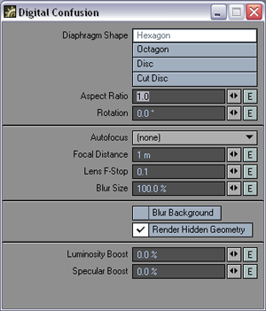
Digital Confusion (Post-processing only)
Lightwave's
built-in Depth of Field effect (Camera
Properties panel)
adjusts which pixels the rendering camera considers in and out of focus.
The Digital Confusion image filter creates the same effect using the similar
controls, but offers several extra features. Adjusting the Focal Distance
and Lens F-Stop still easily
controls the range of focus, but added options include camera lens parameters,
auto-focusing, and ways to fine-tune surface properties.
Since Digital
Confusion is added during the anti-aliasing rendering pass, it will respect
and can actually improve oversampling methods like motion blur and Depth
of Field effects. However, Adaptive Sampling (Camera Properties panel)
may not function correctly with this filter. In this case, you should
use an Enhanced Antialiasing setting (Camera Properties panel).
The four Diaphragm Shape settings, Hexagon, Octagon, Disc, and Cut Disc, determine which pattern Digital Confusion will use when “defocusing” the rendered image. These settings correspond to the actual shape of the camera lens used during this effect. The Aspect Ratio and Rotation angle of the camera lens can also be adjusted to create even more specialized effects.
When using Lightwave's built-in Depth of Field controls, it is sometimes difficult to keep a moving object in focus. Now, instead of using envelopes to animate the focal distance, with Digital Confusion you can simply select a reference object from the Autofocus pop-up menu and the proper focal distance will be computed automatically. This reference object can be either the (target) geometry in the scene, or a null object used to dynamically adjust the focus. When an object is selected, the Focal Distance field becomes disabled.
The Focal Distance setting represents the distance from the camera to the point in space that is in focus. Objects that fall either in front of or behind this area will be rendered out of focus. Just how far out of focus is determined by adjusting Digital Confusion's Lens F-Stop setting. By changing this value, you are adjusting the radius of the area that is in focus. For this value, the smaller the Lens F-Stop size, the smaller the in-focus area will be.
Note: For more information on using the Depth of Field controls, refer to the Depth of Field section of the help file.
The Blur Size setting acts as a multiplier to Digital Confusion's “defocusing” effect. Adjusting this control is similar to adjusting the Lens F-Stop setting, but instead of changing the size of the in-focus area, it determines the amount of blur these pixels will receive. By entering a Blur Size value of 50%, the area out of focus, defined by the Focal Distance and Lens F-Stop setting, will receive only half the computed blur.
If a background image is used in your scene, you may want to activate Blur Background to blur it. However, because the background image is at an infinite distance from the camera, it will always receive the maximum blur amount and will result in much longer rendering times. A more efficient solution is to simply blur the background image in a paint program.
The Render Hidden Geometry feature forces LightWave to ray trace any geometry behind objects in case they go transparent when being blurred. This is a much more accurate representation of the depth of field effect, but can increase rendering times. In multi-pass rendering and compositing, it may be acceptable to not activate this feature, but normally it should be activated.
Note: Double-Sided geometry will not work correctly with the Render Hidden Geometry activated.
Sometimes defocusing the rendered image can cause the effect of surface specularity or luminosity to diminish unacceptably. To offset this effect you can adjust the Luminosity Boost or Specular Boost multipliers located at the bottom of the panel. Any pixels rendered with these surface properties will have their intensity adjusted accordingly.
Depth-Of-Field Blur (Post-processing only)
This filter lets you add a depth of field effect that is based on a fast image filter, without requiring multi-pass anti-aliasing like normal depth of field does (Camera panel). You can adjust the overall strength of the blur, as well as independently choose whether to blur the alpha channel and background.
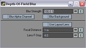
See the
discussion on normal Depth of field (DOF) for information on the Focal Distance
and Lens F-Stop settings. You
can also activate the Use Layout
Lens
option to use the Camera Properties DOF settings.
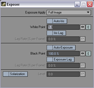
Exposer
This filter
normalizes high dynamic range (HDR) images for using as image maps and
HDR output for displaying in applications that are not HDR-savvy. The
intensity mapping is non - linear, similar to the light response process
in the human eye.
This filter
processes the HDR output created by radiosity renders into better-looking,
brighter pictures. It does this without impacting the accuracy of the
lighting simulation, which can happen if you add ambient light or crank
up lights unrealistically. It is really an essential part of the camera
simulation, for a perfect digital camera. (The Virtual Darkroom filter
is similar, but more complex. It simulates the two-stage process of film
response to light, and print emulsion response to projection through the
film negative.)
Although you can add this filter on the Image Editor, it is of limited use there and more useful as an Image filter on the Processing tab of the Effects panel. This is mainly because most images you load are not HDR images, so pre-processing is not necessary and normal gamma should probably be used, if necessary. Moreover, if you do load an HDR image, it’s probably because you want the extra data. (Using the HDR Exposure filter will eliminate some, if not all, of the extra data.)
The Input Dynamic Range is an informational display showing the High and Low pixel-intensity values encountered in the last processed image. Note that when the panel first appears, this information is not yet known.
If you do not want the filter applied to the Full Image, set the Exposure Apply pop-up menu to Foreground to apply it only to scene items or Background to affect only the background (i.e., where your alpha would be black).
The White Point is the input intensity considered to be the hottest white. Anything above this will be the same white in the output. This control is overridden by the Auto-Iris option, which sets the white point based on the actual input image data. Adjusting the white point is similar to cranking down an iris on a film camera to limit how bright parts blow out in a photograph.
The Black Point, expressed as a percentage of the nominal black point (1/255), is the darkest non-black pixel level in the input image that will be preserved. Anything darker will come out black. The Auto-Exposure option overrides Black Point by using the actual image data to determine a black point in the incoming data. Lowering the black point is similar to increasing the exposure time for a photograph.
Once these values are set, the filter translates the incoming image intensity—in a process very similar to gamma correction—so that the darker colors get more of the output range than the brighter colors. In other words, the filter changes the spacing of intensity levels so more levels are devoted to low intensity, darker details.
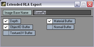
Extended RLA Export (Post-processing only)
This filter saves images in the Extended RLA format, popular for 2D/3D compositing work. The image includes optional depth buffers, as well as masks for which object or surface (material) a pixel came from. Enter the Image Base Name in the field or use the file requester button.
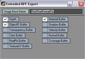
Extended RPF Export (Post-processing
only)
This filter saves images in the Extended RPF format, popular for 2D/3D compositing work. The image includes a few more options then the Extended RLA. Enter the Image Base Name in the field or use the file requester button.
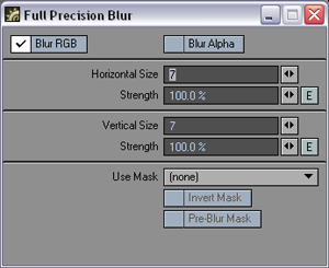
Full Precision Blur
This filter will soften an image by blurring it. Change the Size values to increase the amount of blur horizontally or vertically. The Strength settings determine the amount of the effect. You can also choose whether to affect the RGB (color) and/or alpha data.
You can use the Rendered Alpha (channel) or a Special Buffer as a mask using the Use Mask pop-up menu. If you want the mask computed prior to the blurring, check the Pre-Blur Mask option, otherwise the mask accounts for any blurring. To reverse the mask, check Invert Mask.
The Special Buffer setting on the Advanced tab of the Surface Editor can have a value from 0 to 1, with 0 meaning no blur and 1 meaning full blur.
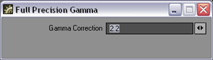
Full Precision Gamma
Display devices have a non-linear relationship between pixel values and physical light intensity—they do not excite the display phosphors linearly. This non-linearity must be compensated for to correctly reproduce intensity. The Gamma Correction value is the exponent value in the correction formula and determines how to convert pixel values to light intensity. The default, 2.2, is a common value used on images bound for video, but is not necessarily the optimum value.
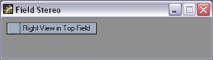
Field Stereo
Rather than using red/blue glasses to create a stereoscopic animation, you can use LCD shutter glasses that work with the fielded nature of TV screens to work their magic. Field Stereo allows you to render separate images for each field so that you get an effect of depth from the separation between the fields. Don't forget to turn on Stereoscopic rendering and Field Rendering in the Camera Properties panel.
HDR Exposure
This filter normalizes high dynamic range (HDR) images for using as image maps and HDR output for displaying in applications that are not HDR-savvy. The intensity mapping is non - linear, similar to the light response process in the human eye.
This filter processes the HDR output created by radiosity renders into better-looking, brighter pictures. It does this without impacting the accuracy of the lighting simulation, which can happen if you add ambient light or crank up lights unrealistically. It is really an essential part of the camera simulation, for a perfect digital camera. (The Virtual Darkroom filter is similar, but more complex. It simulates the two-stage process of film response to light, and print emulsion response to projection through the film negative.)
Although you can add this filter on the Image Editor, it is of limited use there and more useful as an Image filter on the Processing tab of the Effects panel. This is mainly because most images you load are not HDR images, so pre-processing is not necessary and normal gamma should probably be used, if necessary. Moreover, if you do load an HDR image, it’s probably because you want the extra data. (Using the HDR Exposure filter will eliminate some, if not all, of the extra data.)
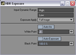
The Input Dynamic Range
is an informational display showing the High and Low pixel-intensity values
encountered in the last processed image. Note that when the panel first
appears, this information is not yet known.
If you do not want the filter applied to the Full Image, set the Exposure Apply pop-up menu to Foreground to apply it only to scene items or Background to affect only the background (i.e., where your alpha would be black).
The White Point is the input intensity considered to be the hottest white. Anything above this will be the same white in the output. This control is overridden by the Auto-Iris option, which sets the white point based on the actual input image data. Adjusting the white point is similar to cranking down an iris on a film camera to limit how bright parts blow out in a photograph.
The Black Point, expressed as a percentage of the nominal black point (1/255), is the darkest non-black pixel level in the input image that will be preserved. Anything darker will come out black. The Auto-Exposure option overrides Black Point by using the actual image data to determine a black point in the incoming data. Lowering the black point is similar to increasing the exposure time for a photograph.
Once these values are set, the filter translates the incoming image intensity—in a process very similar to gamma correction—so that the darker colors get more of the output range than the brighter colors. In other words, the filter changes the spacing of intensity levels so more levels are devoted to low intensity, darker details.
Lscript
and LScript/RT
Both allow you to run an LScript on a finished image.
Photoshop PSD Export
The Photoshop
PSD Export image filter is an image saver masquerading around as an image
filter. Being a filter allows it to have access to all the different internal
render buffers. When you render a frame, a sequentially numbered PSD file
is saved with each of the selected buffers placed into their own channel.
(In Photoshop 6, select the Channels tab, between the Layers and Paths
tabs.)
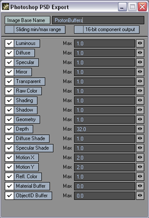 The
Max field determines the maximum value allowed in a buffer. So the acceptable
buffer values are always zero to the Max. All values in the buffer are
divided by Max to normalize them to the range zero to one.
The
Max field determines the maximum value allowed in a buffer. So the acceptable
buffer values are always zero to the Max. All values in the buffer are
divided by Max to normalize them to the range zero to one.
The Sliding min/max range option will dynamically compute the minimum and maximum values of each buffer. The values are computed for every frame so the output buffers will have the widest possible range of values. This is great for still images, but animations should not use this setting, due to the lack of "temporal coherence" (i.e., the images may "pop" from frame to frame).
The 16 bit component output option will save out 16 bits per channel/buffer. Normally, only eight bits are used.
Soften Reflections (Post-processing only)
This filter will blur reflections. The Blend control will Replace the reflection with a blurred version, Average them together, which is more subtle, or use the Maximum of the replace result and the original, which avoids a dark halo, at the cost of a lighter image. You can also blend based on the Alpha channel or the intensity of the reflection (LumaBlend).
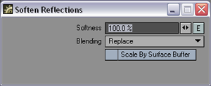
Soften Reflections
can scale the blur based on the surface’s value in Special Buffer 1 (Advanced
tab of the Surface Editor), if you check the Scale By Surface Buffer
option. (A value of 1 means 100 percent.)
Render Buffer Export (Post-processing only)
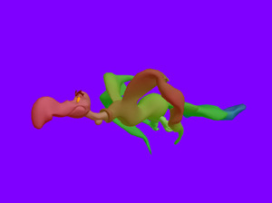
This filter lets you save images from one of LightWave’s internal buffers (Source). The Surface Custom option on the Source pop-up menu will create a grayscale image, where each object surface can have a unique grayscale value. This was designed to allow post-processing effects to be applied on a surface-by-surface basis. A surface’s grayscale value (0-255) is assigned using the Special Buffer option on the Advanced tab of the Surface Editor.
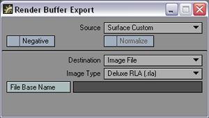
To invert
the image data, check the Negative option. The
Normalize
option is available only for certain Source selections that
don’t normally provide image data, like X Motion. Normalize
scales the values to be 0 to 1.
With the Destination pop-up menu, you can save the selected buffer image as a separate Image File, or replace the Rendered RGB or Rendered Alpha image data. (If you choose Image File, set the Image Type and enter the full path and filename in the File Name input field.)
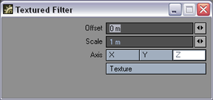
TextureFilter
Use TextureFilter to add the selected texture to the image before use. You could use this filter to add, say, an animated Fractal Noise pattern to a simple black image. Since textures are three-dimensional, particularly procedurals, use the Axis setting to use the X, Y, or Z of the texture. (Note: The differences between the Axis selection can be subtle.)
To see procedurals in viewports:
You can use Texture Filter to see procedural textures in your Layout viewport! Basically, you apply the procedural texture(s) to the image using Texture Filter and then map the image to the surface. Here’s how you do it:
1 First, you need to load an image into the Image Editor. It really doesn’t matter what image you use since it will be obscured by the textures.
2 On the Image Editor’s Processing tab, add Texture Filter. Double-click it in the list window to access its options. Click the Texture button to access the Texture Editor.
3 Change the default initial Layer Type to Gradient. This provides the underlying color. You can leave it white or change it.
4 Add one or more procedural texture layers and set as you would normally.
5 Load your object and open the Surface Editor.
6 Click the Color attributes Texture button. Leave Layer Type set to Image Map on the Texture Editor that appears.
7 Set Projection as you would normally and select your image from the Image pop-up menu. The procedural will now appear in your viewport.
This operation requires a lot of computations and Layout may seem sluggish as it computes the texture.
Note: The image preview window on the Image Editor will show the texture as well. Thus, you can double-click the window to bring up the Image Viewer, from which you can save this compiled image. This can then be image mapped back onto the surface without all of the calculations required with TextureFilter.
If you use an image sequence instead of a still image, you can even see an animated texture! Note that if an animated texture is applied to a still image, it will not appear animated.
Vector Blur (Post-processing only)
LightWave’s normal motion blur (Camera properties) may need long render times because of multi-pass anti-aliasing. Vector Blur, on the other hand, can achieve great-looking motion blur in a fraction of the render time.
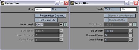
The two
modes, Vector
and Blur,
use motion data that identifies each pixel’s immediate motion in the horizontal
and vertical directions. The Vector mode smears
the pixel out based on the motion information, while the Blur
mode uses the horizontal and vertical data to smush
together the surrounding pixels with that pixel. Blur
affects the pixels around it including backgrounds, while Vector
alters only the pixels of the moving object.
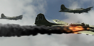
The Blur mode should be used in conjunction with the normal motion blur; however, the Vector mode can be used by itself—you don’t even need to use antialiasing! The result can be drastically reduced rendering time. Below is a comparison between regular motion blur and the two modes of Vector Blur.
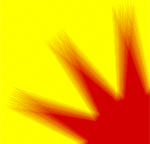
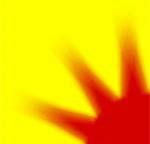

Normal Motion
Blur, Vector Blur: Blur, Vector Blur: Vector
Overlapping Objects
Since objects become transparent with motion blur, the filter needs something in the background of the blur. When Compensate Background is active, the filter does not use the backdrop and attempts to compensate for this absence. This works in most cases, but may not give a very realistic motion blur.
When Compensate Background is not active, the filter uses the backdrop. However, it will not show an object behind another object.
If you have overlapping objects, you may want to do some test renders to see if Vector Blur will provide acceptable results. If not, use LightWave’s normal motion blur.
High Quality Blur
If you uncheck Compensate Background, you can activate the High Quality Blur setting. This provides better quality, but takes longer to render. In this mode, you will only be able to set the Vector Length setting.
Limits
The important thing to understand about using Vector Blur is that it is a post process. As such, hidden geometry can't be blurred and you may see problems with motion blur on shadows and moving textures. However, it can be a great help when used in conjunction with normal motion blur, by giving you better quality with lower antialiasing settings (Camera panel).
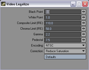
Video Legalize
The Video Legalize filter might be more appropriately named Hot Video, since it assumes that pure black, RGB 0, 0, 0, is mapped to the proper pedestal by the encoding device (e.g., 7.5 IRE for NTSC). The encoding device may not, however, correct hot pixels—that is, colors that exceed certain video specifications. This is where VideoLegalize steps in.
Pixel values are generally scaled into IRE units using the Black Point, White Point and Pedestal settings as follows: Level = Pedestal + (100 - Pedestal) * (pixel - Black) / (White - Black). White is always 100 IRE and NTSC black is 7.5 IRE. Thus, for NTSC, the level would be computed: Level = 7.5 + 92.5 * (pixel - Black) / (White – Black).
Normally,
an RGB level of 0.0 is black and 1.0 is white. If those are used for the
Black Point
and White Point settings, the
level will be 7.5 + 92.5 * (pixel - 0.0) / (1.0 - 0.0) or just 7.5
+ 92.5 * pixel. When the pixel is 1.0, the level is 100 IRE, and when
the pixel is 0.0, the level is 7.5 IRE.
Note: the actual computation is more complex than the above since other operations, like gamma correction, can happen.
The settings default to NTSC encoding, but you may also select PAL from the Encoding pop-up menu. (Note that you also need to click the Default button after selecting a new Encoding item.) You may change the individual settings from their defaults, if desired.
The Correct pop-up menu determines how the image is corrected to fall within the specified limits.
Note: It is highly recommended that you use VideoLegalize (as a post-process image filter) if you plan to use your images for video.
Video Tap (Post-processing only)
The Video Tap filter will save a second image using different camera and render option settings. This is perfect for times when you render a film resolution scene, but you want to preview a video resolution version on your VT3 or other digital disk recorder.
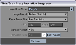
FUN FACTS: Movie-makers often attach a
video camera to a film camera, so they can watch dailies without developing
the film—saving time and money. This filter’s namesake is the video tap
on the film camera.
Virtual Darkroom
The Virtual Darkroom filter simulates the photographic capture of images. It is based on A Model for Simulating the Photographic Development Process on Digital Images, by Joe Geigel and F. Kenton Musgrave in the SIGGRAPH ’97 conference proceedings.
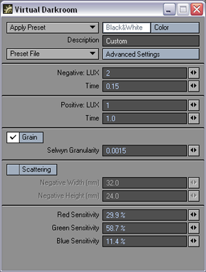
Global settings
are the four controls located at the top. Output Type
specifies whether the output image is Black
and White
(single-plane grayscale) or Color (three-plane
RGB).
Basic
Settings
Basic Settings control everything except for those settings on other tabs.
Negative LUX is the illumination
value for the negative pass—analogous to scene capture with a camera—which
will affect overall brightness. Negative
Time is the exposure time for negative pass, essentially the exposure
setting on the virtual camera. Positive
LUX is the illumination value for the positive (printing) pass.
Think of this as the brightness of the bulb in the enlarger or printing
mechanism. Positive Time is the
exposure time during the printing pass of virtual enlarger.
Enable Scattering will activate the internal scattering effect. Negative Width and Negative Height are the width and height, respectively, in millimeters, of the virtual negative. These values are used in scattering and grain calculations. Enable Grain will activate the grain effect. Selwyn Granularity controls the intensity of the grain. Increasing this value increases grain, decreasing it will decrease grain.
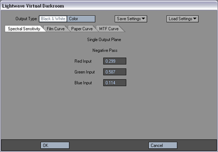
Advanced Settings:
Spectral Sensitivity Tab
If Output Type is set to Color, there will be six sets of RGB percentage controls. Each RGB trio specifies the percentage of the black and white output plane that is contributed by the input image plane named in the control. For example, the RGB trio in the upper-middle defines how the output from the negative passes on the spectral sensitivity module creates the green plane.
If Output Type is set to Black & White, you specify what percentage of the red, green, and blue planes of the input image are used when they are combined into a single black and white image. This transition takes place in the negative (first) pass. During the printing (second) pass, there is only a single input plane, so spectral sensitivity is not used.
Film, Paper, and MTF Curve Tabs
You can enter up to 21 pairs that define the characteristic curve of the
film and paper, and the function for modulation transfer used for scattering
calculations. For each pair, the first value represents log (exposure)
and the second value represents the density.
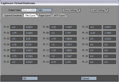
For all
Curve tab entries, points should be entered in order starting with Pt.
01. If Output Type is set to Color,
curves must be set for each output plane by selecting the appropriate
Red Plane, Green Plane, or Blue Plane sub-tab.
LensCap
A very complex image filter that, in the world of 3D imaging, only
the engineers at NewTek were smart enough to put together. Unfortunately,
no one can be told what Lenscap is; you have to experience it for yourself.
Math
Filter
This pixel Filter allows you to use a mathematical formula to adjust the
color in your render.

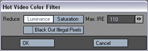
NTSC_Legalize
NTSC_Legalize scans the rendered output for pixels with unsafe values of chrominance signal or composite signal amplitude when encoded into an NTSC color signal. Such illegal pixels can be corrected by reducing their Luminance or Saturation. Alternatively, the pixels can be colored black by activating the Black Out Illegal Pixels option. When applied, the rendered output will have a maximum composite signal amplitude of the Max IRE setting (110 IRE by default) and a maximum chroma amplitude of 50 IRE in compliance with the RS-170A video specification.
Negative
This is not a filter that makes sarcastic comments about your abilities
in 3D, nor does it just sneer at your results, it simply inverts the colors
in your picture.
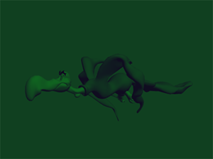
NightVision
This darkens your image and tints it towards green giving a Night Vision-type
look to your image. It also converts the picture to a low dynamic range.
PAL_Legalize
PAL_Legalize scans the rendered output for pixels with unsafe values of chrominance signal or composite signal amplitude when encoded into an PAL color signal. Such illegal pixels can be corrected by reducing their Luminance or Saturation. Alternatively, the pixels can be colored black by activating the Black Out Illegal Pixels option. When applied, the rendered output will have a maximum composite signal amplitude of the Max IRE setting (110 IRE by default) and a maximum chroma amplitude of 50 IRE.
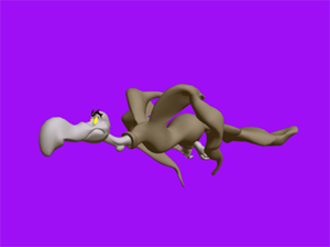
Sepia
Adds a sepia tint to your image while desaturating it.
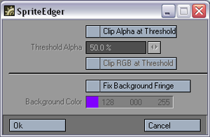
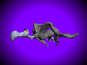
SpriteEdger
The Sprite Edger image filter "unmixes" anti-aliased object edges from the background. It can remove background color fringing if the object is not rendered over black. It can also clip the alpha channel to form a 1-bit (0 or 1) mask. It can even use this mask to clip the RGB imaged edges, setting the pixels to the background color if they are outside the mask.
VidNoise
Adds specks to a rendered image. Beware, this filter converts your render
into a low dynamic range image.
Vignette
Creates an imaginary circle in the middle and then progressively darkens
your image to the outside edge creating a central point of focus. This
filter doesn't like radiosity renders.
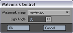
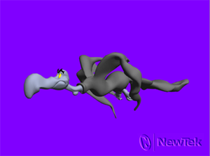
WaterMark
The WaterMark filter embosses an image in the lower-right quarter of the image. You can select any loaded image; however, grayscale images using a black background work best. The Light Angle field determines the direction of the implied light source.

Note: Other filters, like Pixel filters,
may appear on the Image Editor in the list of image filters.
Wave
Filter Image
The WaveFilter Image filter
allows you to apply and adjust image filters, color filters, grain and
matte filters to the entire image, the background, objects only, shadows
only, a special buffer, or a user-definable color range. A powerful interface
with color preview provides the control you need to tweak your image to
perfection.
Note: See the Wave Filter Image section for more information.
Motion Options
See Motion Options Section
Hide Floating Windows On/Off
Since your screen can often get cluttered
with open panels, you can quickly hide/show these floating windows by
pressing the Tab key. This option can also be found under the Windows
drop down menu.
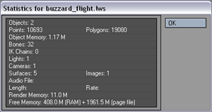
Scene Statistics
Pressing the (w) key will display the Scene Statistics panel, which provides various information about the current scene.