
Reduce Polys + (QemLOSS2 Function)
The Reduce Polys + function (Construct > Reduce : Reduce Polys+) uses a surface simplification algorithm in an attempt to reduce the number of polygons in an object. The plug-in lets you rapidly produce good quality approximations of excessively detailed polygonal models. Reduce Polys + is an excellent way to create low-resolution stand-in objects for scene layout or for multi-resolution models. You can use the object replacement capability in Layout to substitute a low-resolution object in place of an object with a high polygon count when it is far away from the camera.
These plug-in uses routines adapted from Michael Garland's public domain QSlim Simplification Software. The algorithms used in this software are described in the papers written by Michael Garland and Paul S. Heckbert, Surface Simplification Using Quadric Error Metrics, SIGGRAPH 97, and Simplifying Surfaces with Color and Texture using Quadric Error Metrics, IEEE Visualization 98.
Introduction
Many 3D models contain a large number of polygons, especially algorithmically created models (such as those created by implicit surface construction techniques) and models created with 3D scanners and digitizers. Polygon reduction in these types of models is currently a very active research area in computer graphics. Obviously, rendering 3D scenes is much faster when the models contain a minimum number of polygons. Also with the current trend towards sharing 3D worlds over the Internet using VRML, level of detail models (LOD) are becoming absolutely necessary for creating worlds in which the user can browse and interact in a reasonable manner.
This tool provides polygon reduction on objects within Modeler. Only one parameter, the reduction Goal, must be set by the user, the remaining default values should provide good reduction for many objects with a high polygon count. However, to get the best results, the user must understand some of the basic concepts behind the algorithm.
Terminology
The simplification algorithm is based on contractions of vertex pairs. It supports two types of contractions: edge and non-edge contractions. An edge contraction occurs when the vertex pair shares an edge. This is the primary type of contraction that occurs during the reduction stage (in fact, non-edge contractions are turned off by the default parameters). The following figure shows an example of an edge contraction where vertex v1 and vertex v2 are joined to form a new vertex v3. Since v1 and v2 share an edge (highlighted below), one or more triangles will always be removed during this contraction. In this example, two triangles are eliminated from the mesh.
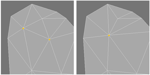
Edge Contraction
Non-edge contractions
let the algorithm join unconnected areas of the object together. The next
figure shows an example of a non-edge contraction (also called aggregation).
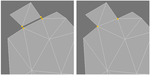
Non-Edge Contraction
In fact, there are two non-edge contractions taking place: v1 and v2 contract to form v5; v3 and v4 contract to form v6. Since by definition the vertices in the contraction pairs do not share an edge (there is no edge between v1 and v2, or the v3, v4 pair), there is no actual reduction in the polygon count of the object. However, since this feature joins previously unconnected areas of the object together, the potential exists for future reductions. Many times this can also provide a better low resolution approximation of an object that has many disconnected regions.
As the algorithm proceeds through each iteration, an approximation of geometric error accumulates at each vertex of the object. If this geometric error is less than the user defined Maximum Error Tolerance, the vertex is marked as a viable candidate for another contraction. Once the geometric error for a vertex becomes greater than the maximum threshold value, it will no longer be considered in any more contractions. During each iteration, the vertex pair with the smallest combined geometric error is chosen for the current contraction.
The algorithm proceeds until the simplified object is reduced to the user's targeted Goal (number of polygons) or until all the vertex errors have become greater than the Maximum Error Tolerance. These two parameters control how much reduction will there will be. The remaining of the parameters control various aspects of the vertex contractions.
Two types of vertices receive special consideration by this plug-in: surface border and boundary vertices. Parameters are provided for you to weight the geometric error for these two special types of vertices:
• A surface border vertex is a point that is shared by two or more surfaces.
• An edge that exists in only one triangle is a boundary edge, and determines two endpoints that are called boundary vertices.
The Surface Border Weight and Boundary Preservation Weight parameters let you weigh the geometric error at these points. The higher the weight, the less likely the vertex will be replaced. Clever use of these parameters (along with some equally clever surfacing) can provide quite a bit of control over the contraction process. The Polygon Area Weighting parameter causes every vertex's geometric error to be weighted by the area of the polygons that contain the vertex. Once again causing larger values (triangles with larger areas) to be less likely to be removed.
To help preserve the shape of these shared borders, weighting of the surface border vertices, using Surface Border Weight, has been added to the algorithm to help restrict movement/replacement of those vertices.
WARNING
Always save your objects before you run Reduce Polys +!
Using Reduce Polys +
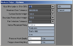
Make sure you have an object in the current foreground layer(s) of Modeler. You also need at least one empty layer, because the existing object remains unchanged, and the reduced object is placed in the first available empty layer. Choose Construct > Reduce : Reduce Polys + and you are presented with the following panel.
NOTE:
Reduce Polys + ignores any polygon selections and works only on the entire object in the foreground layer, including any hidden polygons.
Goal
Goal lets you set the final number of polygons you would like in the simplified object. You may enter either a desired polygon count (an integer such as 1000), or a percent based on the number of polygons found in the original object (a real number with a percent sign at the end, such as 65.2%). If you enter a percentage, it will simply calculate the polygon goal by multiplying that percentage by the total polygon count in the original object. So 100% will mean no reduction takes place, and 0% means the object will disappear completely.
The first major step Reduce Polys + takes is to triple your polygons, which will increase the polygon count, if your model contains non-triangular polygons. A Goal of 100%, however, will reduce the number of polygons back to the original number, but now they will all be triangles. If that reduction doesn't preserve your model's shape well enough, don't hesitate to try percentages over 100%, those models will still be smaller than the tripled original.
NOTE:
Other parameter settings may cause the algorithm to fail to reach the reduction goal.
Maximum Error Tolerance
Maximum Error Tolerance sets the geometric error threshold. A large value (such as the default 1,000,000) almost guarantees that you will achieve the reduction goal in the previous parameter field. Smaller values may preserve the shape of the original object better, however you may not achieve the desired reduction goal entered above.
Surface Border Weight
Surface Border Weight gives you some control over how often and far surface border vertices are relocated during the reduction process. A large value restricts the relocation of points that lie along surface borders, thereby preserving the shape of the border fairly well. Smaller values let the points move farther from their original location, possibly causing the border to change its shape. A value of 0 will not constrain the surface borders at all, and vertices along a border may not end up where you expect when the simplification is finished.
Boundary Preservation Weight
Boundary Preservation Weight allows you some control over how boundary vertices are relocated during the contraction process. A small value let’s the boundary points move farther than larger values. A value of 0 will not constrain the boundary at all, and the object may not look at all like you expect when the simplification is finished.
If you end up with unexpected gaps between non-contiguous polygon surfaces, you can try to preserve those boundaries by increasing the Boundary Preservation Weight. However, you might get better results by merging the edge points together before running Reduce Polys +. You can always just cut and paste the polygons afterward, if the separation was essential.
Pair Selection Tolerance
Pair Selection Tolerance determines whether non-edge contractions are performed during the simplification process. If this value is 0, non-edge contractions are turned off, and only edge contractions will take place during the simplification. Any value greater than 0 will cause non-edge contractions to be possible during the reduction. If you enter a negative number, Reduce Polys + will automatically use 5% of the radius of the object's bounding sphere. This is the value you should use if you want to start experimenting with this parameter.
Take care when changing this value to anything but 0! It is strongly recommended that you leave this at 0 for all complex models with lots of polygons. If you use this, first reduce the model to a fairly small polygon count with it turned off (=0), then reduce the reduction again with a carefully chosen Pair Selection Tolerance, or better yet, just use a negative number. It is a very memory intensive operation.
Vertex Placement Policy
Vertex Placement Policy is best left at Optimal. When a pair of vertices is contracted, the algorithm must decide where to locate the new vertex. The algorithm can use any one of the three final options listed in this selection of buttons. Optimal calculates the new placement based on the location with the least amount of geometric error. Doesn't hurt to experiment with these options though.
Sometimes vertex pair contractions do not preserve the orientation of the faces in certain areas of the contraction, If Preserve Mesh Quality is changed to Yes, the normal of each neighboring face is compared before and after the contraction. If the normal flips, the contraction is penalized greatly by making the geometric error for that contraction very large (so that contraction will probably never take place). In most cases, this will not be a problem, and the plug-in will work faster if this parameter stays set to No. But it's not terribly slow, so it certainly doesn't hurt to experiment with it.
Polygon Area Weighting
If you change Polygon Area Weighting to Yes, the area of the triangle containing the vertex is used to weight the geometric error. This will cause larger triangles to increase the geometric errors of its vertices, so it is less likely to be chosen for simplification.
The Reduce Polys + function displays a progress monitor while it creates the reduced object in the first available empty layer. Here is what happens: first, the object in the foreground layer(s) is copied to the first available empty layer, then all its polygons are converted to triangles using Modeler's Triple command. Next, all vertices and polygons are converted into the necessary data structures needed for the simplification routines, and the copied object is subsequently removed. Once the simplification routine finishes, the reduced polygon object is placed in the previously empty layer.
NOTE:
For additional information, check out http://amber.rc.arizona.edu/lw.
